Welding inverter scheme Instruments
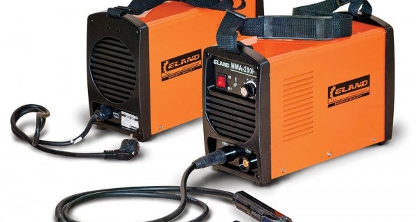
IIST (Inverter Sources of Welding Current) Nowadays, transformer sources, the principle of operation of which is based on a decrease in transformer. Such transformers worked at the frequency of the power grid - 50-65 Hz and were rather bulky devices. The scheme of the welding inverter differs from the transformer and then we will explain exactly what exactly.
Content
The appearance of welding inverters
The procession of the IIST on the planet began in the 90s of the twentieth century and now it is possible to declare with confidence that in the market of welding aggregates both industrial and home appointments are inverter welding plants. Now they are used everywhere:
- in arc welding with uncomplicated and piece electrodes;
- in welding automatic and semi-automatic;
- in welding aluminum parts, plasma cutting and in other types of electric welding.
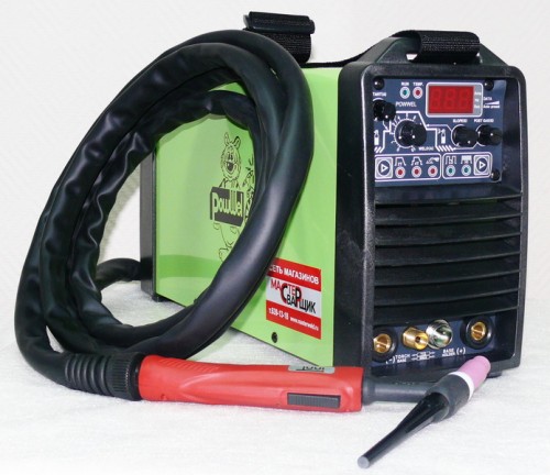
What is a IIST and what does it differ from classic, transformer sources of welding current? This is a welding machine that works on the principle of a computer power supply, that is, as a pulse bp. From transformer units, the welding inverter is much smaller than the sizes and, on the contrary, significantly superior frequencies. That is, if transformer devices operate at 50 Hz (current frequency in the network in the Russian Federation and other countries), then welding inverters have a frequency of 55-75 kHz.
This approach makes it possible to seriously reduce the size of the apparatus, as well as reduce the costs of its production - the coil in the inverter current source is less transformer at times, respectively, less requires expensive copper.
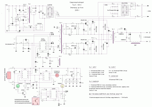
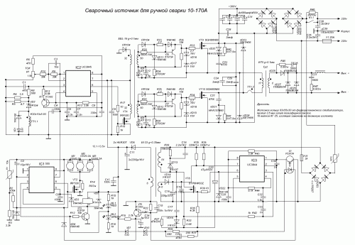
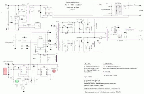
Fundamental and electrical schemes
The schematic diagram of the welding inverter is based on a block of high-frequency transistors operating at a frequency of 55-75 kHz. For these key elements to work, the input current should be compressed on them, and it comes from a high-power diode bridge. The input voltage is straightened to them, and aligned with filter capacitors in such a way that at the output of the first stage we obtain a powerful constant current voltage over 220V.
This electrical circuit of the welding inverter works as a power source for a transistor unit IIST. Transistors operate at an increased frequency in 60-80 kHz, respectively, the lowering transformer will also work at this frequency. Accordingly, this fact allows to seriously reduce the size of the transformer and the entire welding inverter. As a result, the welding machine becomes much less than its classic fellow, but at the same time it retains the same power.
So, if we consider the principle of operation of the inverter welding machine, the procedure for actions performed by the device will be the following:
- AC 220V, obtained from the power grid is straightened by a diode bridge. As a precaution, the interference from the work of high-frequency capacitors does not fall into the network, an interference filter is installed before the bridge that prevents it.
- After that, the current is aligned with capacitors and enters the transistor unit. It should be noted that on capacitors, the voltage of the current will be 1.5 times higher than at the outlet of the diode bridge.
- The constant current is sent to the transistors through the primary winding of the lowering transformer with a frequency, multiple excellent. In fact, we get high-frequency alternating current.
- Next, this current enters a lowering high-frequency transformer, characterized by a large cross section of the secondary winding or using other types of winding material.
- The transformer lowers current to voltage 50-70V. At the same time, the strength of the current grows to grow and may exceed 130a. In handicraft assemblies, transformers with a secondary winding of a copper tin thickness 0.3 and 40 mm width can be used. This approach is due to the fact that high-frequency currents are displaced on the surface of the conductor and the core of the thick conductor do not use, which causes the heating of the conductor.
After that, straighten the current output diodes. The nuance of the work of the output diode is that he has to work with high frequency current, and not every diode will cope with it. In this situation, it is necessary to use high-speed diodes with a recovery time of less than 50 nanoseconds, since ordinary diodes simply will not have time to work, given the frequency of the incoming current.
As a result, at the outlet, we obtain the constant current of low voltage required for welding, but extremely high current.
Such is the schematic diagram of the source of the inverter welding current. In each particular model there are differences laid by the manufacturer, additional schemes that increase the reliability and safety of the device, for example, a thermocontrol unit that protects the main elements of the overheating unit, and also controls the cooling system. But, despite the differences in detail, all inverter welding machines operate according to the above principle.
Types of welding inverters and their schemes
As an example, you can look at domestic welding inverters of Reante. The company supplies both the standard line of inverters of different power and compact versions of the inverters, some of which can fit in a small case. In the same principle there are plasma cutters and argon-arc welding machines of resant.
There are also foreign manufacturers on the market, for example, the German company Fubag. The Germans offer extremely reliable aggregates, both multifunctional and highly specialized. Plus, German devices can boast a large number of additional features. This is forced cooling, work on low facilities, an additional welder's adjustment, microprocessor control and much more.
In addition, if you wish, you can collect the welding inverter with your own hands. The assembly process will not take much time, it is enough to have initial knowledge of electrical engineering. Inverter schemes are in open access, the manufacture of a printed circuit board directly the most powerful block will not be much labor. The availability of the element base for the manufacture of the inverter is very high, but the lowering transformer will be best done independently to get rid of the problem of high heating of the transformer. The main thing is not to forget about the interference filter to protect your own power grid.

