DIY stress stabilizer Useful advice
Voltage differences negatively affect any household appliances. This is especially true of high-precision electronics regulating the operation of heating devices.
Content
In order to level the current at home, the voltage stabilizer is used. In the simplest version, it works on the principle of the risk, increasing and lowering the resistance depending on the current force. But there are more modern devices that fully protect equipment from voltage jumps. How to make them and talk.
Voltage stabilizer and its principle
For a more detailed understanding of the operation of the device, consider the electrical current components:
- current force
- voltage,
- frequency.
The current is the amount of charge that passed through the conductor for a certain period of time. Voltage, if you explain very simple, equivalent to the concept of work that makes an electric field. The frequency is the speed with which the electron flux changes its direction. This value is characteristic solely for alternating current, which circulates in the power grid. Most household appliances are calculated on a voltage of 220 volts, and the current strength must be 5 amps, and the frequency is 50 hertz.
In most cases, household appliances have a permissible plug on each of the parameters, but any defense is calculated that the conditions of operation of the instruments will be unchanged for a long time. In our network, current fluctuations occur almost all the time. The amplitude is up to 2 A according to the strength of the current and up to 40-50 V, voltage. The current frequency is also different from 50 Hz and ranges from 40 Hz to 60 Hz.
This problem is associated with many factors, but the main one among them is the remoteness of the end user from the source of electricity. As a result, sufficiently long transportation and multiple transformation, the current loses stability. This defect of the power grid is present not only with us, but also in any other countries that use electricity. Therefore, a special device was invented to stabilize the output current.
Types of voltage stabilizers
Since the current is the directional movement of particles, to adjust it:
- mechanical method
- pulse method.
Mechanical is based on the law of Ohm. Such a stabilizer is called linear. It consists of two knees interconnected by a row. The voltage is fed to one knee, passes through the ride and falls on the second knee, from which it is already it further. The advantages of this method is that it allows you to accurately establish the output current parameters. Depending on the purpose, the linear stabilizer is upgraded by additional spare parts. It is worth noting that the device is effectively coping with its task only if the difference between the input and output current is small. Otherwise, the stabilizer will have a low efficiency. But even this is enough to protect the household appliances and protect yourself from a short circuit in the event of a network server.
The pulse voltage stabilizer is based on the principle of amplitude current modulation. The voltage stabilizer circuit is designed in such a way that there is a switch in the circuit that automatically breaks the chain at equal intervals. This allows you to feed the current with parts and evenly accumulate it in the condenser. After it charges, the aligned current is fed to the instruments. The disadvantage of this method is that it does not allow to specify a certain amount. Nevertheless, it is often often encountered by impulse rising-lowering stabilizers that are optimally suitable for domestic use. They align the current within a little lower or slightly above the norm. In both cases, all current parameters do not go beyond the valid plug.
It is important to note the separation of devices on:
- single phase voltage stabilizer,
- three-phase voltage stabilizer.
After redistribution in the transformer, a three-phase line comes out, it usually goes to a distribution panel to a single house. Next, the standard phase and zero are already going from the flap in the apartment. Thus, most household appliances are calculated on a single-phase network. Therefore, in typical apartments it is advisable to use a single-phase stabilizer. In addition, it costs 10 times cheaper than three-phase, even if you collect it with your own hands.
Voltage stabilizers for giving can be three-phase. Especially relevant for powerful pumps, cultivators and heavy construction equipment. In this case, it is necessary to make a stabilizer designed for a current transformation under a specific device. In practice, this is quite difficult. Therefore, it's easier to take it for rent. The use of the above instruments is temporary, therefore it makes sense to spend time and money on a three-phase voltage stabilizer.
The main elements of the voltage stabilizer
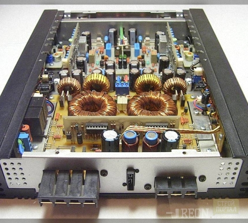
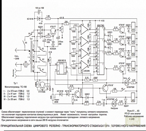
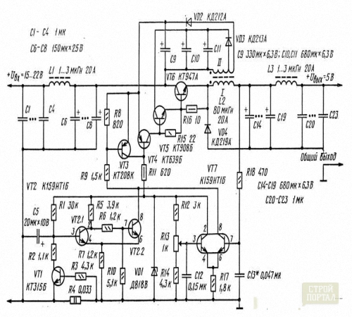
In order to collect a simple current equalizer, you will not need any special skills or specific details. Voltage stabilizers for home consist of:
- transformer
- capacitors
- resistors,
- diodes
- wires for connecting the chip.
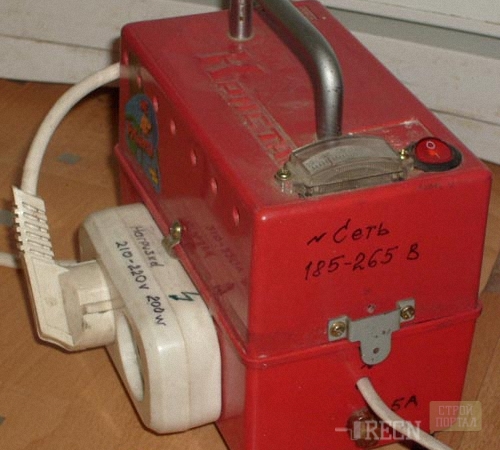
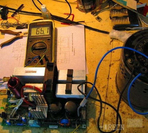
Ideal if there is an old welding machine. It is very easy to remake it into the voltage stabilizer, the same will not need to buy additional parts and design the housing for the microcircuit. The video at the end of the article is devoted to this issue. But, unnecessary welding is a big rarity, so we consider the procedure for creating a voltage stabilizer from zero. Since the pulse stabilizer does not allow to carry out the exact setting of the parameters, we will consider the linear voltage stabilizer.
Production of self-made voltage stabilizer
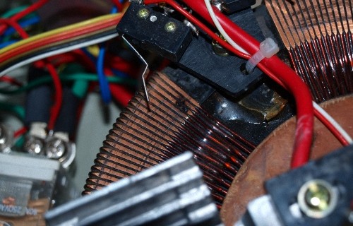
Its base is a transformer. In practice, transformers are much smaller than massive booths for leveling high voltage coming from the power plant. They are two coils forming inductive electromagnetic communications. Simply put, the current is fed to one coil, charges it, then an electromagnetic field occurs, which charges the second coil, with which the current is next. This relationship is expressed by the formula:
| U. 2 | = | N. 2 | = | I. 1 |
| U. 1 | N. 1 | I. 2 |
- U. 1 - voltage on the primary winding,
- U. 2 - voltage on the secondary winding,
- N. 1 - the number of turns on the primary winding,
- N. 2 - the number of turns on the secondary winding,
- I. 1 - current current on the primary winding,
- I. 2 - Current power on the secondary winding.
The formula is not ideal, as it allows either to lower the voltage or increase it. In 90% of cases, a low voltage current comes to the consumer. Therefore, it makes sense to immediately make a boost transformer. Inductive coils for it are sold in electrical engineering stores either on any flea market. It is important to note that the number of turns must be at least 2000 thousand, since otherwise the transformer will be very warm and soon burns. In order to select the power of the transformer, you need to measure the voltage in the network. For calculations, we take the value of 196. The formula acquires this type:
| 220 | = | nS |
| 196 | 2000 |
Consequently, in order to level the voltage to the required value, the second coil with the number of turns is needed: 220x2000 / 196 \u003d 2245. In this formula, there are certain flaws, as part of the electrical energy is lost on the heating of the winding. Therefore, the fork of calculations is 5 V, i.e. The value of 196 is permissible to round, it can change to 191 V or 201 B, and the number of turns should not be changed.
Now consider the second part of the formula:
| 220 | = | nS |
| 196 | 4 |
As can be seen from the formula, the output voltage force will be 220x4 / 196 \u003d 4.4 A. Most electrical appliances admits a plug in 1 A. Therefore, the value obtained is sufficient for the normal operation of the technique.
The voltage stabilizer, the energy in which is increased by the specified value is ready. But if the network occurs in the network, the formula will take the following values:
| nS | = | 2245 |
| 236 | 2000 |
So the output voltage will become 236x2245 / 2000 \u003d 264 V. The current will increase proportionally.
| 264 | = | 4,47 |
| 236 | 4 |
This will lead to the breakdown of most electrical appliances.
To eliminate this defect, we use the Ohm's law:
- U- Voltage,
- I- current,
- R- resistance.
264 \u003d 4.47хR, R \u003d 264 / 4,47 \u003d 60. This formula suggests that ideally the resistance of all elements in the system will be 60 ohms. If you lower the resistance, then the voltage to decrease:
220 \u003d 4,47хR, R \u003d 220 / 4,47 \u003d 50.
To change the network resistance, the device is used, called Pereostat. Naturally, it is uncomfortable to regulate it manually. Therefore, it will take the voltage chip-stabilizer on which the path of the electric current will be marked after exiting the transformer.
The easiest way is to remove the current from the transformer to the condenser. It is advisable to use 12-16 capacitors of the same container. This will accumulate the current and make it more uniform. Further, all condensers are connected to the row. The current power in the network after the transformer will be within 4.5-5 A, and the desired voltage should be 220 V. Consequently, we have the formula R \u003d 220 / 4.75 \u003d 46. With averaged indicators, resistance should be 46 ohms.
To achieve smoother alignment, it is desirable to establish several parallel retakes. Thus, connecting into one thread after capacitors, the chain must be distributed on 4.6,8 individual branches connected to the risostami. In this case, the formula R / number of retakes should be used. If you do a chain of 6 risostats, then according to the data presented, each of them must have resistance in 8 ohms.
After passing the retakes, the chain is again assembled into one stream and is displayed on the diode. The diode is connected to the usual outlet.
All specified manipulations refer to the wire on which the phase is located, zero simply skip directly to the outlet.
The method specified with the referee is quite archaic. Much more effectively use the usual protective shutdown device instead. The current from the transformer is fed to the RCD, zero is also connected to the UZO. Next, it goes directly to the outlet.
In the event that the voltage or the current will increase in the investigation of the voltage jump, the circuit will open the circuit, and the household appliances will not suffer. During the rest of the time the transformer will qualitatively align the current.
With an increased voltage, you will need a lower transformer. It is going to the analogy, by the exception that the winding on the second coil should be made of a thicker wire, otherwise the transformer burns.
Most effectively assemble both transformers. Moreover, there is a downgrain-rising design. In the first case, you will need manually switching the wires, in the second - the process is automatically. As can be seen, the voltage stabilizer is not difficult, but work with electricity involves the limit level of caution.
Tips for working with self-made voltage stabilizer
Important: The described scheme is ideal for permanent conditions, but in the power grid, there are often interruptions and races, both up and down.
Therefore, when assembling a voltage stabilizer, we recommend that it is recommended to repel from the parameters of a particular technique, i.e.:
- consider wiring around the apartment
- if the repair is not assumed, to establish extension cords under certain groups of electrical appliances with similar parameters,
- connect each group to a separate stabilizer.
Any household appliances either on the back, or in the passport contains statements about power requirements. Stripping from specific figures is much easier to create an effective stabilizer, as there is no need to adapt to the network. Another useful gadget is an electronic voltmeter. It is advisable to connect it to the scheme of the stabilizer for visual control over its work.
For the housing, any material is suitable other than wood. Frequently, homemade stabilizers are placed in plastic food containers.


