Current and voltage transformers: Purpose, Device, Principle of operation Useful advice
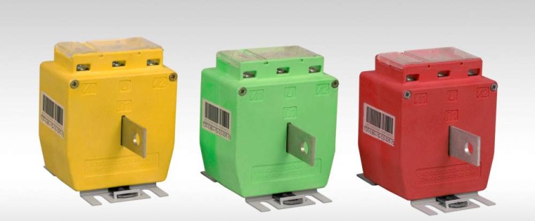
In order to bring the current and voltage parameters to the required standards, use special electrical devices called transformers. Depending on the purpose, the device and the accuracy class of the current and voltage transformers are divided into several types. In this article, consider measuring voltage and current transformers, which are installed in the circuits of electricity accounting.
Content
Current transformer: general concepts
In the accounting circuit, the current transformers (TT) of the accuracy class is not lower than 0.5 nominal power of which are selected in accordance with the network parameters. The purpose of this device is to ensure control of electricity consumption. Types of current transformers: TPL, TOL 10, TPOL, T-0.66, TFSM and others.
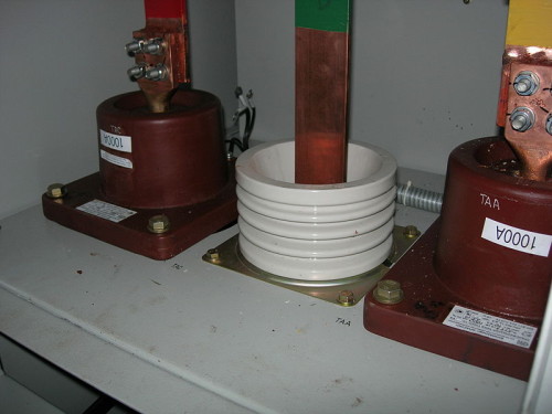
TPOL-10 current transformers with primary winding 1000 A
The design of current transformers has the following features.
- The primary winding is performed as a thick bus (the number of turns is minimized). Such a design allows you to optimize the transformation coefficient and improve the operation of the transformer.
- The wire of the secondary winding is wound on the basis made of magnetic material with a large cross-sectional area. The secondary winding current is usually 5a (sometimes 1a).
Types of current transformers
Three main types should be highlighted.
- Dry transformers: they have a primary winding has a physical connection with the secondary. The secondary current value directly depends on the transformation coefficient.
- Toroidal: installed on a bus or cable and therefore do not have the primary winding. The primary current flows through the conductor in the middle of the case. Such transformers with a split core (can be opened without disconnecting the primary chain) can perform a protective function (from the network of the network).
- High-voltage (oil or gas): can be with primary winding or without it (tire type). In addition to the measuring, there may be an additional secondary winding - to ensure the operation of relay protection.
Verification of current transformers
Verification TT is performed in accordance with GOST 8.217-2003. The regulatory document provides for the following operations:
- conducting an external inspection (the integrity of the case, the presence and correctness of the labeling, passport data is also checked;
- magnetization: There are several ways, one of which prescribes a smooth increase in current (for 2 minutes) on the primary winding from 0 to 100% of the nominal value at a complete nominal load and then smooth decrease to zero;
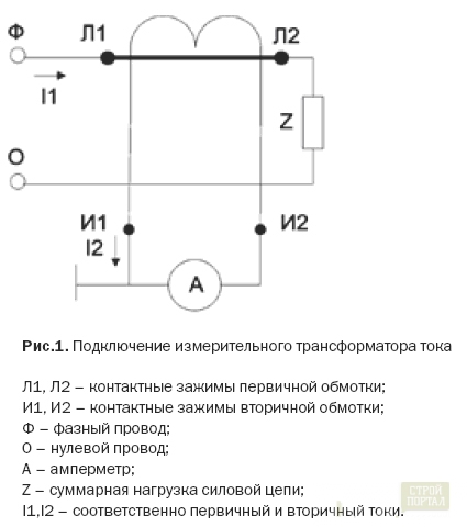
- checking the correspondence of the polarity of the terminals of the primary and secondary windings (according to the calibration scheme);
- determination of current and angular errors: performed using a reference current transformer, load shopping and comparison device (comparator).
The results of the verification are issued by the protocol and evidence. In certain cases, sealing is provided.
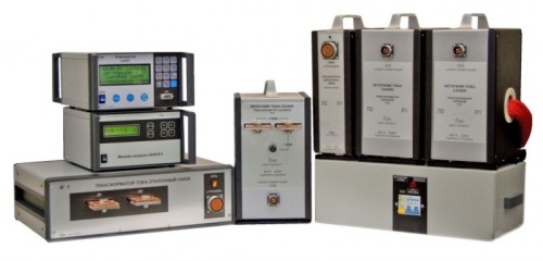
Stand for calibration current transformers
Voltage transformers: device and principle of operation
The current and voltage transformer device is largely similar: the primary and secondary windings are wound around the steel core scored from sheet steel. Voltage transformers (TN) are single and three-phase. Their purpose is to reduce the voltage to the required level. The measuring three-phase network establishes a group of single-phase (for each phase) or a transformer, in the case of which three primary windings are collected and three secondary. The output voltage of three-phase measuring TN - 100 V. The nominal voltage of the primary winding depends on network parameters (35 kV, 10 kV, 6 kV).
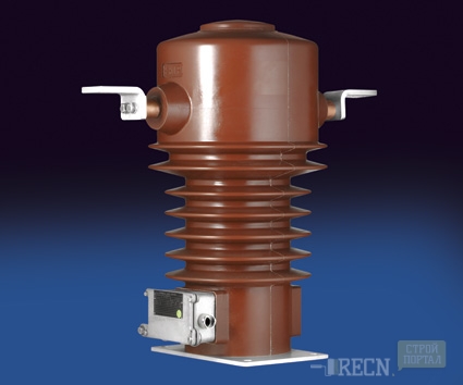
Voltage transformers, except for measuring, are used for:
- connecting measuring instruments and other equipment to ensure its safe operation;
- to expand the limits for measuring connected devices;
- to ensure the work of fire-fighting automation and relay protection.
The current and voltage transformers, the inclusion schemes of which are no different from lower transformers, are measuring if they are located in front of the counters and have an accuracy class of at least 0.5 (for commercial metering).
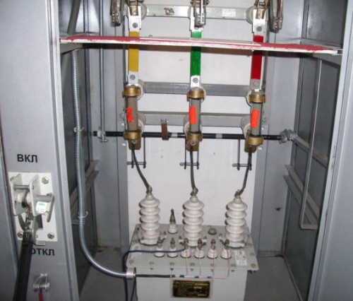
Voltage transformer in cell
Some types of voltage transformers
- KNF-110: Oil transformer consisting of two cascades on the general magnetic lines.
- NOM-35 or Znom-35: The design of such transformers is sealed, inside the case - oil, the level of which is 25-30 mm below the lid. They are not equipped with oil and wizard.
- NTMI-6: transformer with neutral isolated. Its active part consists of single-phase transformers placed in a common case. Inside the case - oil, for the topping of which there is a special cork on the lid. In addition, there are primary and secondary windings on the lid. An additional secondary winding is used to connect alarm and protection. Working occurs when it is closed to any of the phases of primary windings to the ground.
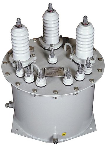
- We are-10: are made on the voltage of the primary winding of 10 and 6 kV, on the secondary - 100 V.
- NTMK-6 (10): Construction with a three-sided magnetic pipeline. The rods are high and low voltage windings connected by the "star", while the zero point has its own conclusion. The winding of the open triangle is not provided. NTMK-6 (10) is intended only for electricity metering chains.
Verification of voltage transformers
TTN calibration is performed in accordance with GOS Method 8.216-211. The procedure provides:
- external inspection, in which the propulsion, the presence and compliance of the marking, isolation integrity, the presence of labeling plates are checked;
- definition of errors: performed using a reference voltage transformer, load shop and comparator.
The results of the verification are issued by the protocol and evidence. On the housing (in the place intended for this), the seal is installed.
In conclusion, a video on the topic "Current and voltage transformers: assignment", where it will be described about the design of NTMI-10.


