Device and connecting fluorescent lamps Lighting
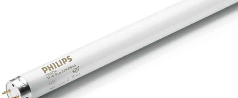
The production of fluorescent lamps occupies second place in the world among sources of artificial light. Every year more than 1 billion pieces are produced. The enormous popularity of these products is explained by low electrical energy consumption and a decent operational period.
Content
Varieties of devices
Fluorescent lamps are produced in a variety of forms. They are divided into:
- tubular;
- ring;
- U-shaped;
- ultraviolet;
- compact.
Tubular lamps have a form similar to a straight tube. Recognize these products are quite easy in the tubular shape of the base. The dimensions of fluorescent lamps are marked with the letter "T" and a digit that denotes a diameter equal to 1/8 of the inches.
Thus, the diameter of the fluorescent lamp T4 will be 13 mm (25.4 * 4: 8). If you need to purchase a light bulb with a diameter of 26 mm, then a product with marking T8 is suitable.
Ring fluorescent light sources are distinguished by the base, which consists of four pins. Depending on the diameter of the rings, the lamps are three sizes.
U-shaped lamps are devices that have a small length, and the bases are located only on the one hand.
Ultraviolet products are an alternative solution to incandescent lamps. The main scope of application is in biological and photochemical irradiators.
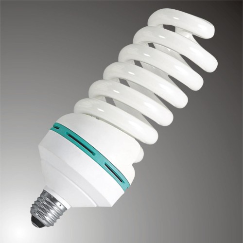
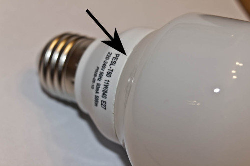
The main difference of compact luminescent lamps is a small size. In some cases, these light sources are denoted by the letters "CCL". Due to the minimum heating temperature, this type of lamps is used in chandeliers and lamps.
Luminescent lamp work principle
Regardless of the differences in light sources on external parameters, they have similar features. In particular, the device of the fluorescent lamp involves the presence of the following elements:
- electrodes;
- luminescent coating (phosphor);
- inert gas with mercury couples in flask.
In essence, the luminescent lamp is a hermetic flask. The gases in it are selected in such a way that it does not need huge energy costs to maintain the ionization process. For permanent luminescence, the lamp must create a glowing discharge.
This is done by supplying a voltage of a certain amount to the electrodes located on both sides of the flasks. Each electrode "equipped" with two contacts that are connected to the current source. This is the heating of the space near the electrodes.
In fact, the diagram of connecting fluorescent lamps is such a sequence of actions:
- heating electrodes;
- the supply of high-voltage pulse;
- support for optimal voltage for the glow discharge.
Thanks to the glowing discharge in a flask coated with a phosphor, an invisible ultraviolet glow occurs. The main purpose of the luminofora is the offset of the frequency range of light into the visible spectrum.
Often the voltage that is available in the electrical network is not enough for the normal functioning of fluorescent lamps. This problem is solved by using two devices:
- choke (limits the strength of the current to the optimal indicator);
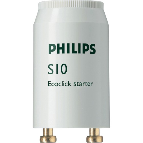
- starter (prevents the lamp burning, adjusting the power of the electrodes).
There are two main ways to connect fluorescent lamps:
- with the help of an electromagnetic ballast;
- using electronic ballast.
Connecting a lamp with an electromagnetic ballast
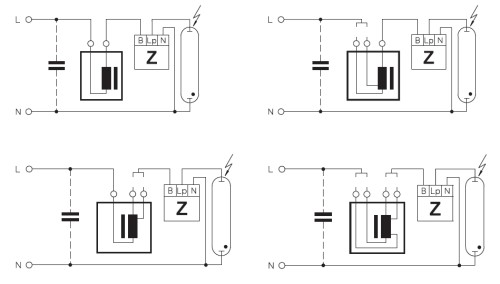
This connection scheme is on:
- throttle into the rupture of the supply chain of threads that increasing the luminescent lamp;
- starter parallel to electrodes.
The starter is a neon light source with a small power. This device has bimetallic contacts and has a substitute from an alternating current. Compound of throttle, starter contacts and filaments of the electrodes are carried out in a sequential order.
Alternatively, the starter can use the regular button from the electrical call. In this case, the voltage supply to the lamp is performed by pressing and holding the button. After Ignoring the lamp, the button should be released.
The process of incorporating a lamp with an electromagnetic ballast is as follows:
- when connecting to the network, electromagnetic energy is accumulated by choke;
- electricity flow is carried out using starter contacts;
- the current passes through the threads of the heating of the electrodes made from tungsten;
- electrodes and starter are heated;
- there is a blank of bimetallic starter contacts;
- this process is accompanied by the emission of energy, which has accumulated in the throttle;
- there is a change in voltage on the electrodes, and the lamp is lit.
To increase the efficiency and suppressing interference, which occur when lamp starts, two capacitors are installed. The smaller size is placed inside the starter and is intended to be sprinkling and improving a breakfast pulse of neon.
The advantages of connecting a luminescent lamp with an electromagnetic ballast include:
- ease of device;
- increased reliability;
- low price.
Disadvantages of this technology:
- solid weight;
- long launch lamp (up to 3 seconds);
- ineffective work at low temperature;
- increased consumption of electrical energy;
- the noisy functioning of the choke;
- flication with a frequency of 100 Hz, which is dangerous for sight.
Connecting a light source with electronic ballast
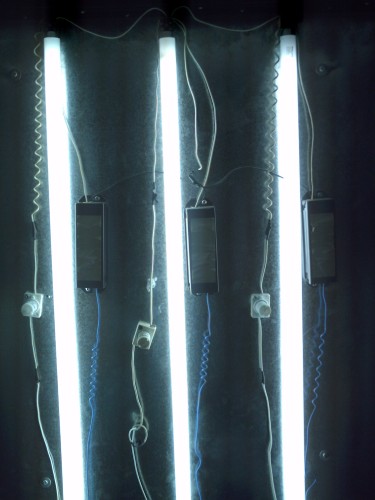
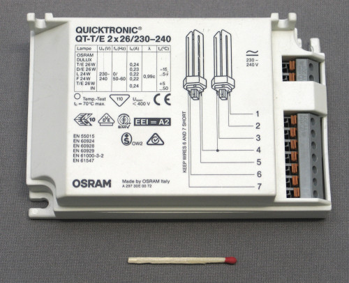
The more high-tech and economical option is the use of a woofer device, which is called an electronic ballast. Thanks to the connection of fluorescent lamps without a throttle and the starter, there are almost all disadvantages inherent in devices with electromagnetic ballast.
In particular, this method of connecting the luminescent lamp is characterized by:
- lack of a flicker effect;
- low electricity consumption;
- rational heating of electrodes;
- excellent efficiency;
- light launch lamps in low-temperature rooms;
- automatic adaptation of a start-adjusting device under the parameters of the light source;
- long operational period of lamps.
Fluorescent lamps are slight weight. They can be placed in a standard base and screw in the usual cartridge.
The disadvantages of the use of devices with an electronic ballast include:
- complex connection scheme;
- serious requirements for component products.
Now about how to connect a luminescent lamp with an electronic ballast. By constructive features, this device is similar to a network voltage converter. To obtain high-frequency alternating voltage, a small-sized inverter is used.
The minimum heating of the electrodes is achieved with the highest frequency. The converter begins to work at a maximum frequency. The inclusion of the lamp occurs in a parallel oscillatory circuit, which has a lower frequency, rather than the initial indicator of the converter.
In the process of launching the lamp, the frequency is reduced and the voltage increases on the oscillatory circuit. This leads to the heating of the electrodes and the subsequent occurrence of the gas discharge. As a result of the closure of the oscillating circuit, the light bulb starts glowing.
Comparing the two options, you should state the fact that the lamps with electronic flow-regulating devices are a more preferred light source. Significant savings are achieved when replacing the starter and choke with an electronic ballast. Moreover, the luminaire case can be left the same.
Removal of the throttle and starter
This procedure can be performed when lamp breakdown. The causes of this phenomenon can be:
- combustion flasks;
- the combustion of the starting device.
It is possible to determine the reason for the appearance of the luminescent lamp. The presence of the darkened ends indicates that the combustion of the flasks occurred. If the flask did not darke it, then it may have happened the launch of the trigger.
To find out this, the lamp must be disassembled. This uses a knife or screwdriver. This procedure is carried out very carefully, because the flask can burst in the hands. No need to make tremendous effort.
Opening the lamp, carefully considers the starting mechanism. Usually there are six wires inside the lamp:
- two feeds going to the circuit from the base;
- four connecting with the flask and arranged pairwise on the edges of the board.
The lack of a spectacle and nagar or molten wires indicates that the scheme is a working. Most likely, the flask burned.
Next steps are as follows:
- with the help of bruises, the scheme is withdrawn;
- the board should remain most of the wiring;
- to test the performance of the circuit, a working lamp is taken, identical in power;
- four wiring that connected with the flask are lengthened, attached to the running lamp and are isolated;
- two feed wires are also lengthened and connected to the network;
- if the lamp caught fire, the scheme is a worker;
- we remove the starter and throttle from the old lamp;
- install the scheme in your place.
Another of the malfunction of the fluorescent lamp may be a break of a tungsten thread. When the light source is enabled, the thread heats the gas, and the phosphor begins to glow. Over time, tungsten gradually evaporates and settles on the walls of the lamp.
The integrity of the tungsten thread is checked using a conventional tester, which measure the resistance of the conductors. If, when contacting with the output ends of the fluorescent lamp, the instrument's scale shows the resistance of 9.9 Ohm, then this indicates the health of the thread. If the instrument readings are zero, then there is a thread break.
The main reason for the cliff of tungsten thread is its thinning as a result of an increasing voltage that passes through it. Increasing the voltage negatively affects the starter, because of which the lamp begins to blink.
Video about the connection of the fluorescent lamp:

