Ground Contour: Description and Calculation Useful advice
Almost all modern houses are equipped with all sorts of electrical engineering, which is part of our daily life. But in the event of an insulation disorder, it can turn out of an indispensable assistant in equipment representing a real threat to life. So that it does not arise, the grounding contour is arranged in the houses.
Content
Which is a ground loop and why it is needed
Grounding is a specially equipped connection with the soil of the inadvertent parts of electrical appliances, which are not in good condition, in the case of insulation disorders, can get under it.
The fact is that the electric current rushes to the other side where the resistance is the most. In case of disruption of electrical insulation, it goes to the housing. Thanks to this, malfunctions may be observed, up to the final failure. But the worst thing is that if a person touch the surface, which is now under voltage, it will get a deadly discharge.
Due to the grounding circuit, the voltage will be distributed between the subject and man. Moreover, because the resistance of the body is much higher than the resistance of the grounding circuit, then the imperceptible amount of current will pass through it, and everything else will go to the ground.
Therefore, when it, it should be remembered that in order for the current to go on it, its resistance should be minimal.
Earth contour device, its types
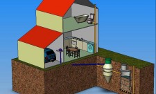
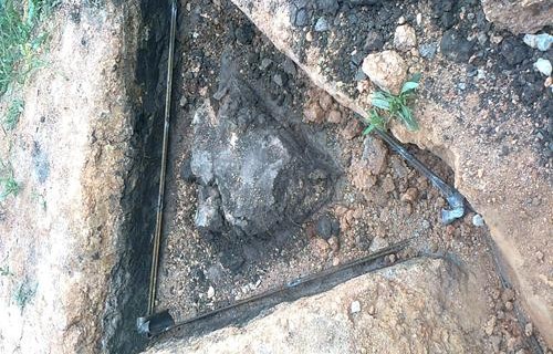
Often, the ground is electrodes in the form of metal pipes that are connected to each other with a metal rod and plunge into the ground. All this design is connected to the house shield using a metal strip.
The distance from the surface of the Earth, to which the electrodes are plunged, depends on which depths are underground water. The closer they are to the surface, the higher the grounding system. In this case, its remoteness from the building should be from 1 to 10 m, not more and no less.
For the arrangement of the grounding contour in a private house, not only the pipes, but also smooth fittings, steel corner, and a heap, are suitable as electrodes. At the same time, they must have a form that allows them to unhindered to score them into the ground, as well as a cross-sectional area exceeding 15 sq. M.
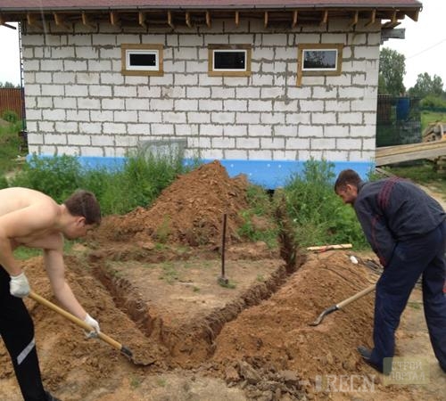
Electrodes are mostly positioned in the form of a geometric shape. It may be square, triangle, rectangle or just a chain. The form depends on the number of pipes, ease of installation of the grounding circuit and the area that needs to be covered. In some cases, the equipment has all over the perimeter of the house.
It is important to remember that the grounding system should necessarily have a deeper level of the labeling of the Earth.
It is possible to build the ground contour with your own hands from what is in the house, but it is easier, of course, to buy ready-made equipment in a specialized store. Its minus lies in sufficiently high cost, and the advantage is in convenience and durability.
There are two main types of grounding contours:
- traditional;
- digid.
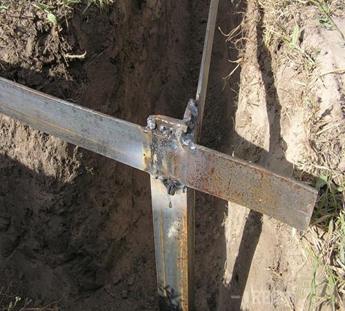
In the first case, the system is made of electrodes, one of which is located horizontally, and several vertically. The first is usually made of steel strip, and the second of the reinforcement or pipes. All electrodes have extremely valid values \u200b\u200bin size.
If the grounding is placed in a residential building, the equipment should be installed where the least there are people, for example, from the northern side of the structure, where there is a shadow longer and more often, and the humidity in the ground is constantly present.
Cons of the traditional ground loop:
- big labor intensity and complexity;
- black steel, from which the structural elements make are subject to corrosion, which is rapidly developing in wet land;
- because The equipment is in the upper soil layer, which is subject to the effect of seasonal temperature drops, as well as moisture and drought, its parameters sometimes become unacceptable.
The deep view of the ground is delivered from many minuses of traditional. It is manufactured in production in the form of a modular-pin system. Advantages:
- thanks to the factory manufacture, meets all standards and requirements;
- serves for a very long time - several decades;
- due to the great depth of clogging the electrodes, in any weather it has a stable value of the resistance to spreading current;
- does not need a frequent observation of the state;
- the calculation of the grounding circuit is extremely simple, however, as installation.
At the end of the work, you need to check whether the installed equipment meets existing requirements. It is also necessary to measure the ground loop in order to verify the quality of all compounds. The study is carried out by an experts of any laboratory that has a license, and after they make a conclusion. On the grounding circuit, the photo of which are presented in the article, the passport is given, as well as the test protocol and access to use.
Before making a ground loop, you need to purchase high-quality materials, because the electrical installation will be reliable only if each element is reliable.
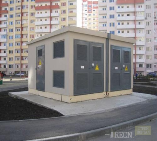
Outdoor earthing contour
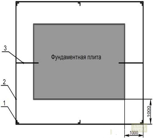
The system is designed for the transformer substation and is a closed loop consisting of several electrodes located vertically and a horizontal earthing. The latter is made of steel strips of 4x40 mm.
The grounding circuit should have a total resistance equal to 40 m, not more, and the soil is a maximum of 1000 m * m. According to the established rules, an increase in value is permissible, but not more than 10 times. From this it follows that with the specified soil resistance, to obtain a value of 40 m, it is necessary to set vertically 8 of the five-meter electrodes made from a circle with a diameter of 1.6 cm, or 10 three meters, the material for which served as a corner of steel 5x5 cm.
The outer circuit of the grounding must defend from the wall of a building or foundation on which there is a transformer booth, not less than a meter.
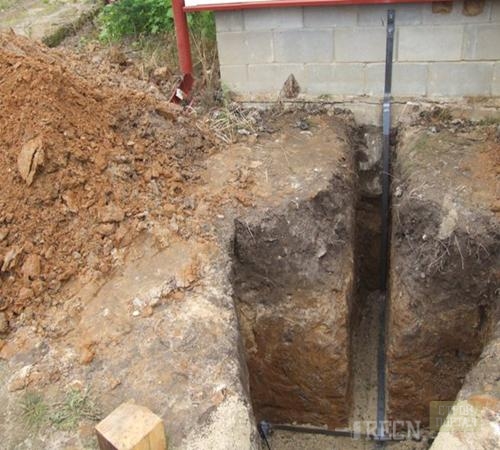
That ground element, which is located horizontally, is placed in a trench at a distance of 70 cm from the surface of the Earth. The strip is put on the narrow part, i.e. On the edge.
Protection of the transformer from the impact of lightning
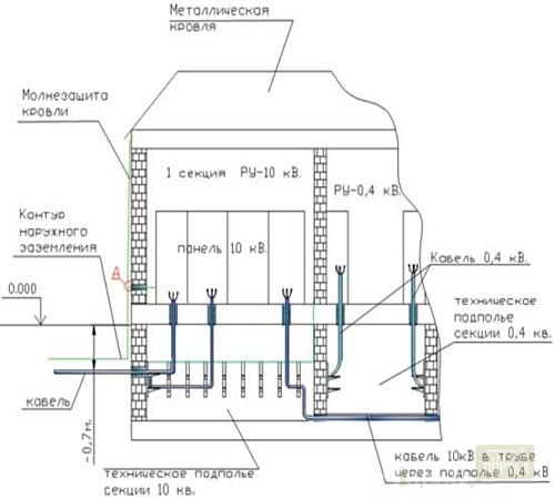
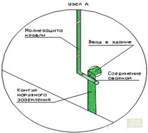
If the roof is made of metal, protect the transformer from lightning is possible as follows: the roof is associated with the grounding system from opposite sides, in other words, in those places where the steel strip is included in the transformer substation. The conductor uses 8 mm in diameter. But it is best to design a lightning game on the roof of the transformer.
The band used as a horizontal element of the system running along the outer wall of the building must be protected from mechanical impact and damage, as well as from the appearance of corrosion.
Internal ground contour
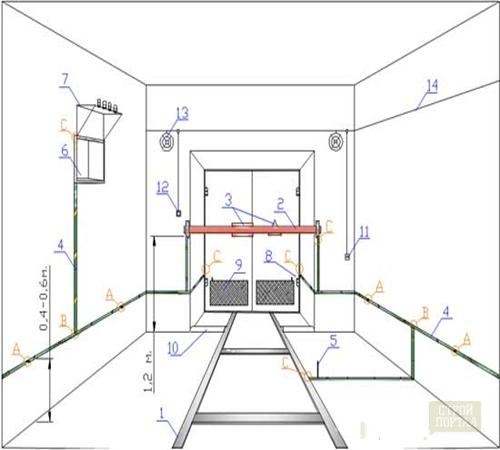
The transformer substation is often equipped with three chambers, less often they are combined into one. On the entire perimeter of each chamber, the ground bar is laid. It is necessary in order to make secure all metal parts of the inner design that are under voltage.
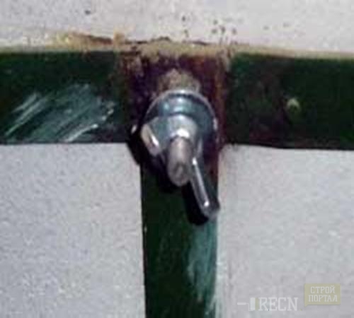
It is attached to the wall to the wall or dowels, or by special holders, the gap between which is equal to 60-100 cm. The floor distance should be 40 cm. All disassembly parts of the design are attached with bolts, other elements - by welding. In the portable earth, the so-called "lamb nut" is used. As a flexible grounding jumpers, an uninsulated PVZ wire is used. This provides the visible integrity of the connection.
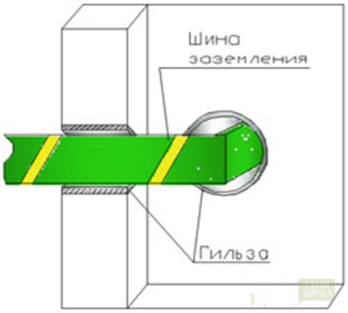
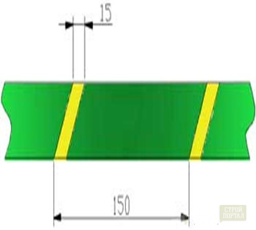
Ground and zero conductors deployed through the walls are close using special sleeves. From the inside they are filled with a specially intended non-combustible mixture. After laying, the strip is painted in a certain way - a green background and on it through an interval of 150 mm yellow stripes 15 mm wide.
In that chamber where the transformer is directly located, the grounding system is shut-off like this:
The circuit of the grounding circuit has the following notation:
- A chamber profile in the floor to which the power transformer is installed.
- Removing fence.
- Signs of warning about the danger, fixed on the fence.
- Bus internal grounding system.
- Transformer grounding tire.
- Recess in the wall for tires 0.4 square meters.
- Tire mounting assembly 0.4 kV.
- Ground ground with jumpers.
- Current ventilation holes in the gate.
- Masual handing board.
- Socket.
- Light in the room.
- Lighting lamp.
- Network 220 V.
A - the point in which the portable ground is joined. The M8 bolt is welded to the ground turbine and equip it with two washers and "nut-lamb" appropriate size.
B - the point in which the grounding tires are connected.
C is a point in which grounding tires are connected to metal structures.
Ground contour, video:


