Repair of welding inverters Instruments
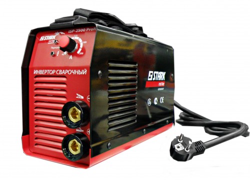
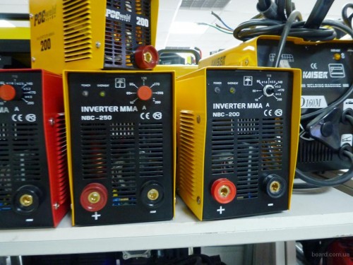
Today, welding machines have small and very compact dimensions. This became possible due to the use of inverter schemes as their foundation. At the same time, powerful field transistors are used instead of power switching elements. Below we will analyze in more detail the principle of operation of the inverters. This will be enough to understand the essence of the work of most devices of this type and the method of their repair. As an example, a welding inverter of domestic production will be considered.
Content
The main components of the welding inverter
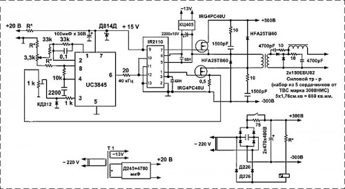
Most of the welding inverters are, in fact, the source of direct current, equipped with a short-circuit protection and thermal shell. A part of the device intended for the current conversion is made by a full-time scheme. Its frequency is approximately 100 kHz. The device has the ability to adjust the current by changing the sign of the well control pulse. The current converter has four keys consisting of four parallel field transistors. Each of them is located on separate radiators of the welding inverter. The repair scheme of the apparatus is presented below.
The device and technique of operation of the unit:
- The multicore transformer wire of the transformer having a silk braid is wound directly on the core.
- The sequence system includes a throttle.
- The current rectifier is made on a two-stroke scheme. On each shoulder there are two diode assemblies with marking 60cpq15, as well as four with 30cpq150 marking. Each of them is installed on a separate radiator.
- The part, referred to as the "soft inclusion scheme", is represented in the apparatus in the form of a delay relay of the complete charge of the capacitors of the power rectifier. At the same time, the main working part is an electromagnetic relay that closes one powerful transistor.
- Directly rectifier consists of the following details:
- one GBPC3508W bridge;
- six parallel to the connected electrolytic capacitors of the 460 MCF400B brand. The bridge is installed on the radiator.
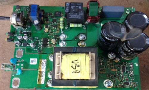
On the same control board are placed two schemes. The first is soft inclusion, the second - control of the converter. There is still a power supply for 15 volts and a condenser module that is part of the charging transducer chain
The control circuit includes the following elements:
- Current adjustment circuit and short circuit protection. They are made on two LM393 chip comparators. In this case, the current sensor is fixed on the iron ring with the winding, and the plus from the power of the converter passes through it. A similar scheme can be seen when repairing a FUBAG welding inverter.
- The control scheme also has a clock generator on the TL494 chip. It is able to give two phases of clock pulses, each of which has a frequency of about 100 kHz. In this case, the diagram does not use latitude and pulse modulation. The device produces pulses with constant duty. The scheme has a pair of comparators. Each of them is connected thermal protection sensors.
- Among the control circuit elements there are also two output drivers built on the basis of the IR2112 board. There are clock impulses on their inputs. They change the duty cycle in the driver. Sources of pulses are comparators of short-circuit protection and current control. Driver outputs are connected to pulse transformers. Control pulses from the secondary windings of these transformers are fed to the keys of the converters.
Basics of repair
To successfully conduct troubleshooting in the devices of this type, certain knowledge is needed in electronics and at least a small experience in this case. Despite this, the repair of welding inverters is available to anyone.
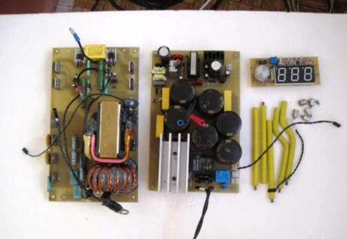
For repair, you will need two instruments - this is an arrow autometer and an oscilloscope. If everything is on hand, you can start working, which usually begins with disassembly of the device and the subsequent inspection of internal parts. Most welding inverters consist of several separate modules:
- Input rectifier.
- Output rectifier.
- Key management fees.
- Enclosure with a fan.
Consider each of the modules a little more.
Input rectifier
The input rectifier module is a large GBPC3508W diode bridge, which is installed on the radiator. He, in turn, attached to the control board from below. When repairing the capacity of the bridge, despite its supernators, is checked by ringing. To make it easier to work easier, it is recommended to immediately remove the radiator and the bridge.
Output rectifier
There is a board with a pair of radiators in the output rectifier module, and power diode assemblies are installed on them, which are very rare. Their amount on the radiator may be different - usually does not exceed four pieces. In addition, this module has a transformer and choke. In the aggregate, diode assemblies can give 240 amperes of DC. When repairing welding inverters, diodes are usually nicknamed in this module, which allows you to find a damaged element. At the same time, it is often used by the method of dropping, because Diodes are problematic differently. To do this, a soldering iron with suction will be useful. After replacing all faulty diodes, this module can be considered serviceable.
Key module
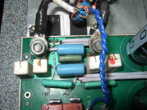
As for the key module, it consists of four groups of transistors. They have four semiconductor components. Each group is set on an insulating strip on its radiator. This module also has smoothing filters of the rectifier (6 pieces) in the form of electrolytic capacitors that feed the converter.
Operating procedure:
- The faulty transistor is often visible to the naked eye. Externally, it usually has hacking, a crack or burned conclusions.
- If the fault is visually invisible, then the arrow autometer is used to detect. To do this, you must first check whether the device is turned off from the network, after which the device is activated in the mode with the resistance measurement limit of KOM X1 and is selected by any group.
- Next, using the device, it is necessary to determine the resistance value between the electrode, where the carriers (drain) and the source of the current carriers are flowing. Between them there is a counter-parallel diode, which, with a good transistor, must be successfully nicknamed.
- If the breakage occurred due to short circuit, the faulty transistor is detected by dropping. It will be relevant when repairing a welding inverter of resant.
Checking the health of transistors
- If all transistors are successfully nicknamed, it does not mean that they are all working. Therefore, it is necessary after a transclon to check them for openness. To do this, be disappeared from each shutter to one end of leveling transistors, put a minus tester on the source of the transistor, and plus for stock. The device must show high resistance.
- Then you need to quickly touch the shutter tester and reappear it to the drain. These manipulations should lead to the fact that resistance will fall almost to zero. If this happened, it means that the transistor has been successfully opened.
- Now you need to check that the transistor has been successfully closed. To do this, with the help of a tweezer, a shutter is closed with a drain or source, after which the resistance is being made again, which this time should jump almost indefinitely.
- If this happened, you can check another transistor in the one described above. Otherwise, after a call, it is necessary to reveal a faulty item for subsequent replacement to a good part.
- If all transistors have been checked successfully, the ends of the leveling resistors can be soldered to the shutters. This should be done with each group in this module. This is useful, for example, when repairing the Telwin welding inverter.
Key Management Board
This module is considered the most difficult. Its working capacity affects the functioning of other components of the welding machine. For the repair of this board, you need a device called an oscilloscope. It allows you to check the presence of key control signals of the key module. Often, power transistors cease to work due to a malfunction of the driver elements. Therefore, they should be checked when repairing an ometer. Directly transistors are usually always working. If defective are detected during the inspection of the items, they should be dropped and replaced with new ones.
Other malfunctions
- The weakest "link" of welding machines is considered a terminal block. Welding cables are connected to it. If, with a large value of the welding current, the connection has bad contact and the wires are strongly heated, then it is destruction or combustion of insulation at the ends of the windings, and this leads to a closure. In this case, the repair of the welding machine is carried out by extinguishing the heating compound. In addition, contact surfaces are cleaned.
- One of the frequent malfunctions is poor welding current adjustment. To get and inspect the mechanism responsible for this, you just need to remove the casing. Usually inspection is enough to detect the cause of the fault. After all, the tool has a simple device, and finding its main components will not be problems. Even when repairing Blueweld welding inverters.
- Overheating of the welding machine is a rather serious malfunction with which further work is extremely recommended. High temperatures lead to the combustion of insulation, and because of this coil, the coil winding is closed, and a closure occurs. If the breakdown is insignificant, then you only need to locally set the insulation of the coil wire. With the most serious breakdowns, you should completely rewind the coil. It is important that the wires are the same sections. Without it, do not save the original characteristics of the device.
- One of the known breakdowns is spontaneous shutdown of the device. This is essentially a protective mechanism from closure. When repairing this service, you must first disable the device from the network, then find a defective place and eliminate this malfunction by restoring insulation, replacing the capacitor and if necessary for other parts.

